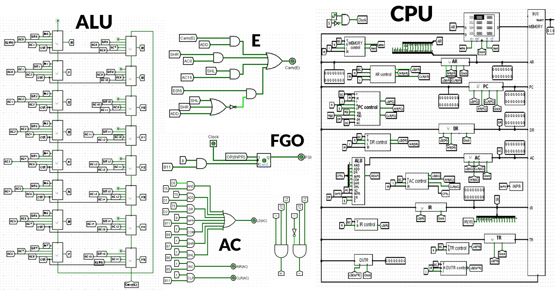
Morris Mano Basic Computer Design using Logisim
This project is part of a Computer Organization course and aims to design a functional CPU, enabling it to solve mathematical problems and run simple programs.
Hardware Components
The Morris Mano Basic Computer consists of the following hardware components:
- Memory Unit: 4096 words, each 16 bits wide.
- Registers: Nine registers including AR (Address Register), PC (Program Counter), DR (Data Register), AC (Accumulator), IR (Instruction Register), TR (Temporary Register), OUTR (Output Register), INPR (Input Register), and SC (Sequence Counter).
- Flip-Flops: Seven flip-flops representing various control and status flags: I (Interrupt), S (Stop), E (Enable), R (Read/Write), lEN (Input Enable), FGI (Input Flag), and FGO (Output Flag).
- Decoders: Two decoders: a 3 x 8 operation decoder and a 4 x 16 timing decoder.
- 16-bit Common Bus: Used for data transfer between different components.
- Control Logic Gates: Responsible for control signals generation and management.
- Adder and Logic Circuit: Connected to the input of the Accumulator (AC) for arithmetic and logical operations.
Built With
The Morris Mano Basic Computer was designed using Logisim, a digital circuit design and simulation tool. Logisim provides a visual environment for designing, simulating, and testing digital circuits.
